A process of how to model with 2D graphics files. The following is 2D:

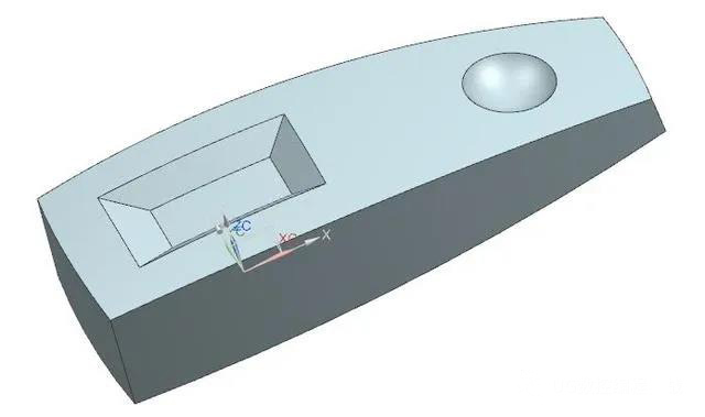
First of all, I saw such a 2D. If I want to model, I first analyze and clarify my thinking. According to the entity, I can see roughly six sides, up and down, left and right, front and back.
1. Below-plane.
2. Above-curved surface: the surface needs to be drawn separately, and the related constraints are mainly carried out through sectionC-C and sectionD-D.
3. Left, right, front and back-plane: There is draft on the plane. In this case, extrude+draft is generally used to draw. You can also draw the corresponding curve and draw with the corresponding surface command, but the process is cumbersome.
After the general image idea is determined, take a look at the details, mainly a square and a circle image, which does not affect the overall image, draw separately, and the idea is completed.
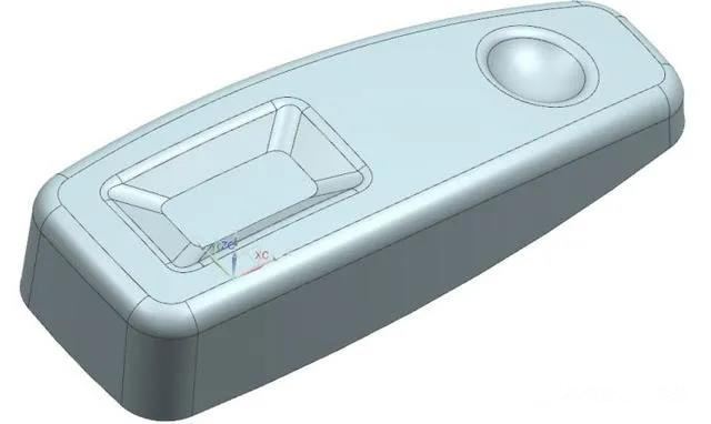
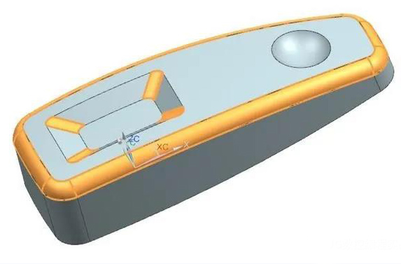
The following is the finished rendering, please refer to:
Tips:
1. Coordinate system position selection: generally select the place where the starting point of the dimension is the most or the symmetric center of the symmetrical figure. If you look at the picture, the intersection of sectionC-C and D-D is the best.
2. The auxiliary curve we use when drawing pictures should be converted into auxiliary lines (dashed lines) in time, which is particularly important for complex sketches.
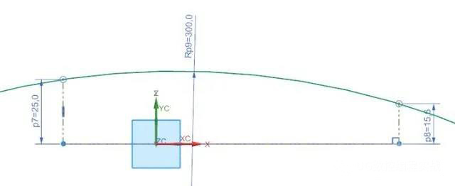
Coordinate origin: up and down symmetrical, left and right according to section D-D P7 =81+26/2.
The sketch image on the bottom surface is complete.
Tips:
1. Up and down symmetry:
The upper arc mirror goes down
The center of the two arcs on the left and right is on XC
2. When trimming the curve, pay special attention to whether there are any short lines remaining in the corners
3. When the constraint point is on a straight line, a better habit is to select the straight line first, and then it is faster to select the point.
Section
D-D production, because after our coordinate system is selected, Section D-D can directly choose X-Z plane
Tips:
When making the right surface, the drawn curve is generally a little longer than the size, and the surface made later will be a little larger, which is convenient for the corresponding addition and subtraction. Except for size constraints.
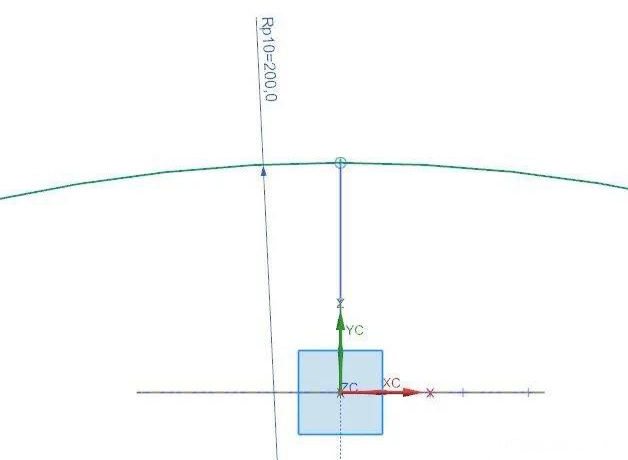
Section
C-C production, because after our coordinate system is selected, Section C-C can directly select the Y-Z plane.
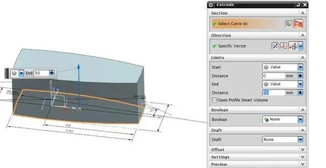
Extrude the solid of our main body.
Tips:
The height of the Extrude should be greater than the highest point of the product as much as possible (the highest dimension is marked as 25, and the height here is 50), so as to facilitate the corresponding addition and subtraction operations. Except for size constraints.
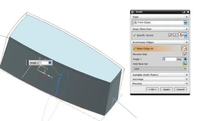
Draft the angle of the question.
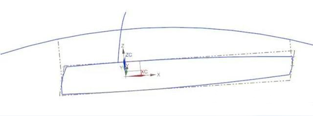
The constraint curve on the top surface has been drawn
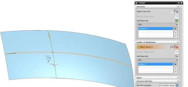
Top surface production: use the command swept.
Tips:
In the command box on the right, check the Preserve shape as much as possible, so that the surface produced is more in line with the constraints of the curve we drawn.
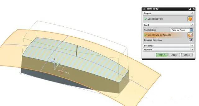
Cut our main body with the surface we swept out to complete the basic image of the upper surface.
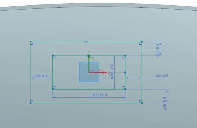
Draw the detailed image of the square on the left side of the product. According to Section C-C and section D-D, the image of the square projected on the bottom surface can be constrained. The picture above is a sketch drawn on the X-Y plane.
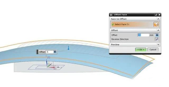
Section C-C size R200, R195 and section D-D
For R300, R295, we use offset-5 on the upper surface to complete the surface with a smaller R, and the finished effect is as shown in the figure below.
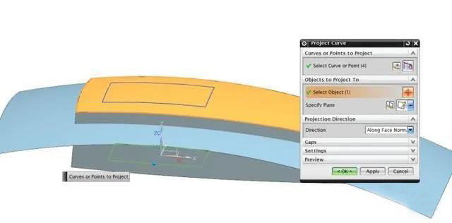
Project the larger rectangle just drawn on the lower surface onto the surface of the R300.
Project the smaller rectangle just drawn on the lower surface onto the surface of R295.
The image of the solid after hiding the main body is shown in the figure.
Through
Curve draws the four slopes in the figure above.
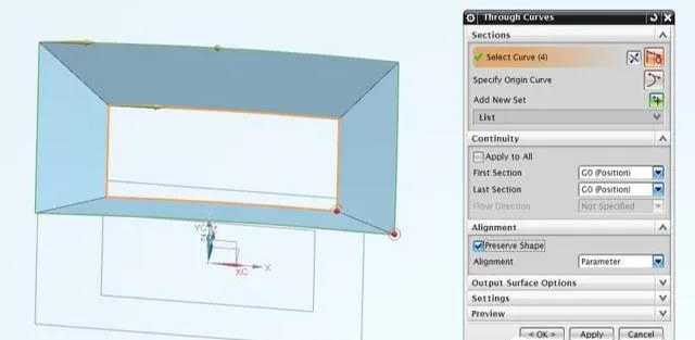
Tips:
1. Note that the starting point and direction of the upper and lower rectangles must be the same, otherwise the graphics will be distorted
2. Preserve shape must be selected, otherwise there will be no segment between every two faces, smooth transition, and there is no way to chamfer.
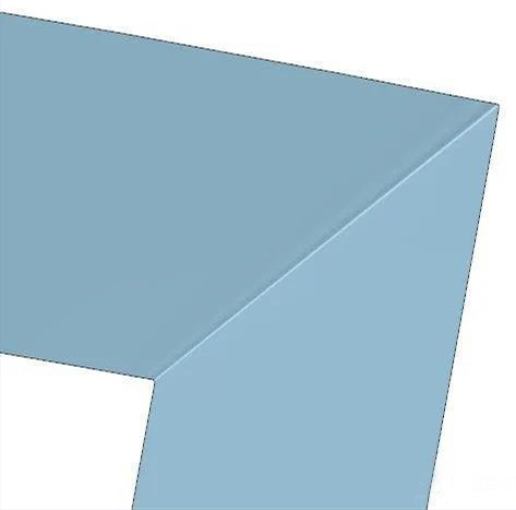
Check Preserve shape on the left, and uncheck Preserve on the right
shape, please pay attention to the difference at the corner.
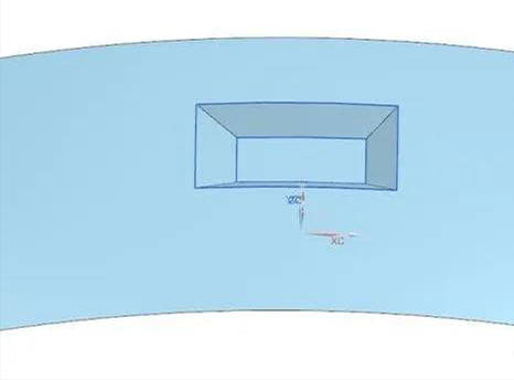
Display the surface whose offset distance was -5 before.
After trimming the faces of the four newly created segments, as shown in the figure above.
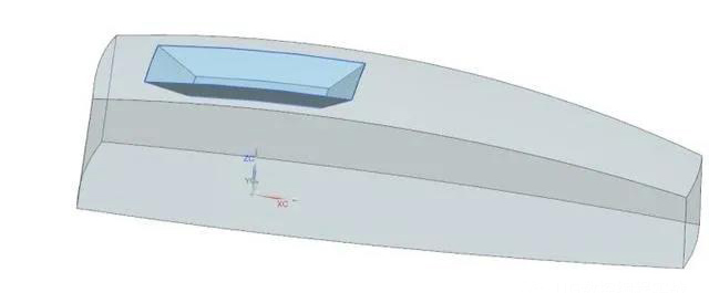
After sew the two planes, change an entire surface.
Shows the solid body of the product, you can see the overall image as shown above
Patch the entire surface after sew to the main body.
Draw the center of the sphere on the right and insert a point.
Select the point we have marked with the size and draw the sphere.
Perform Boolean subtraction on the body and sphere.
Get our overall image, only chamfering and shell.
Tips:
1. Choosing the order of chamfering and shell: See which chamfer radius and shell wall thickness is bigger, make the larger one first. For this figure, chamfer the corners a bit bigger, and chamfer first.
2. Multiple chamfers with different radii, drawn in order from large to small
Note that when selecting the part boundary, the direction of the material side mainly depends on whether the remaining material is outside or inside the curve.
If you'd like to speak to a member of the Anebon team, please get in touch at info@anebon.com
Post time: Mar-10-2021